Preliminary Specification
This document describes the core concepts of the Elan8 DSL. The language is subject to change as we continue development. This is an invitation to collaborate, not a frozen contract.
Note: Full grammar (BNF/Pest/EBNF), complete keyword lists, formal semantics, and parser implementation details are not published at this time.
Elan8 DSL Specification
What is the Elan8 DSL?
The Elan8 DSL is a declarative Architecture-as-Code language that lets you define system architectures in a text-based, versionable format. It provides syntactic sugar over SysML v2 concepts, optimized for authoring UX first, with analysis capabilities built in.
The language is designed to be:
- Human-readable: Write architecture like code, not like formal specifications
- Git-friendly: Optimized for version control, diffs, and code reviews
- Validatable: Architecture can be checked automatically, just like code
- Multidisciplinary: Model software, electronics, and mechanical systems together
What the Elan8 DSL Does Not Try to Do
The Elan8 DSL is intentionally focused. It does not attempt to:
- Replace system design or engineering judgment
- Provide complete modeling of all system aspects
- Generate code automatically (though this may come later)
- Replace existing tools like PLM, CAD, or simulation software
- Be a general-purpose programming language
Instead, it focuses on making architecture explicit, versionable, and checkable.
Core Concepts
The Elan8 DSL is built around a few key concepts:
Naming Convention
The DSL uses a simple but important naming convention:
- Uppercase identifiers (PascalCase) define types — reusable definitions like
part MotorControllerorinterface Power24V - Lowercase identifiers (snake_case) define usage/instances — actual components in your system like
part motor_controller: MotorController
This convention makes it immediately clear what's a type definition versus an instance, and helps the language distinguish between reusable definitions and concrete usage.
part
Structural decomposition — components, subsystems, modules
port
Interaction attachment points (directionless)
interface flow
Physical interaction (power, signals, data)
interface message
Discrete message exchange
across / through
Physical variables (voltage, current, etc.)
message
Packet / dataframe definitions
capability
Resource / suitability definitions
connect to
Bind ports via compatible interfaces
bind to
Deployment / assignment based on capabilities
A Minimal Example
Here's the power supply example from the screenshot above, showing how you define a component with internal parts and connections:
// Power Supply Unit - Converts 230V AC to DC rails
@doc "Power supply unit converting 230V AC to multiple DC voltage rails"
part PowerSupply {

    // 230V AC input port
    port ac_input: Power230V

    // DC output ports
    port power_3v3_out: Power3V3
    port power_5v_out: Power5V
    port power_12v_out: Power12V

    // Internal power conversion stages
    @doc "AC to DC conversion stage"
    part ACDCConverter {
        port ac_input: Power230V
        port dc_output: Power12V
    }

    @doc "3.3V voltage regulator"
    part VoltageRegulator3V3 {
        port input: Power12V
        port output: Power3V3
    }

    @doc "5V voltage regulator"
    part VoltageRegulator5V {
        port input: Power12V
        port output: Power5V
    }

    // Internal connections
    connect ac_input to ACDCConverter.ac_input
    connect ACDCConverter.dc_output to power_12v_out
    connect ACDCConverter.dc_output to VoltageRegulator3V3.input
    connect ACDCConverter.dc_output to VoltageRegulator5V.input
    connect VoltageRegulator3V3.output to power_3v3_out
    connect VoltageRegulator5V.output to power_5v_out
}
This example shows:
- Component structure with multiple ports (ac_input, power_3v3_out, power_5v_out, power_12v_out)
- Internal decomposition (PowerSupply contains ACDCConverter, VoltageRegulator3V3, and VoltageRegulator5V)
- Explicit connections between ports, including branching (one output connected to multiple inputs)
- Documentation annotations using
@doc
This matches exactly what you see in the screenshot above — the code on the left renders as the block diagram on the right.
Visual Representation
The Elan8 IDE renders your DSL code as a visual block diagram. Here's how the power supply example looks when visualized:
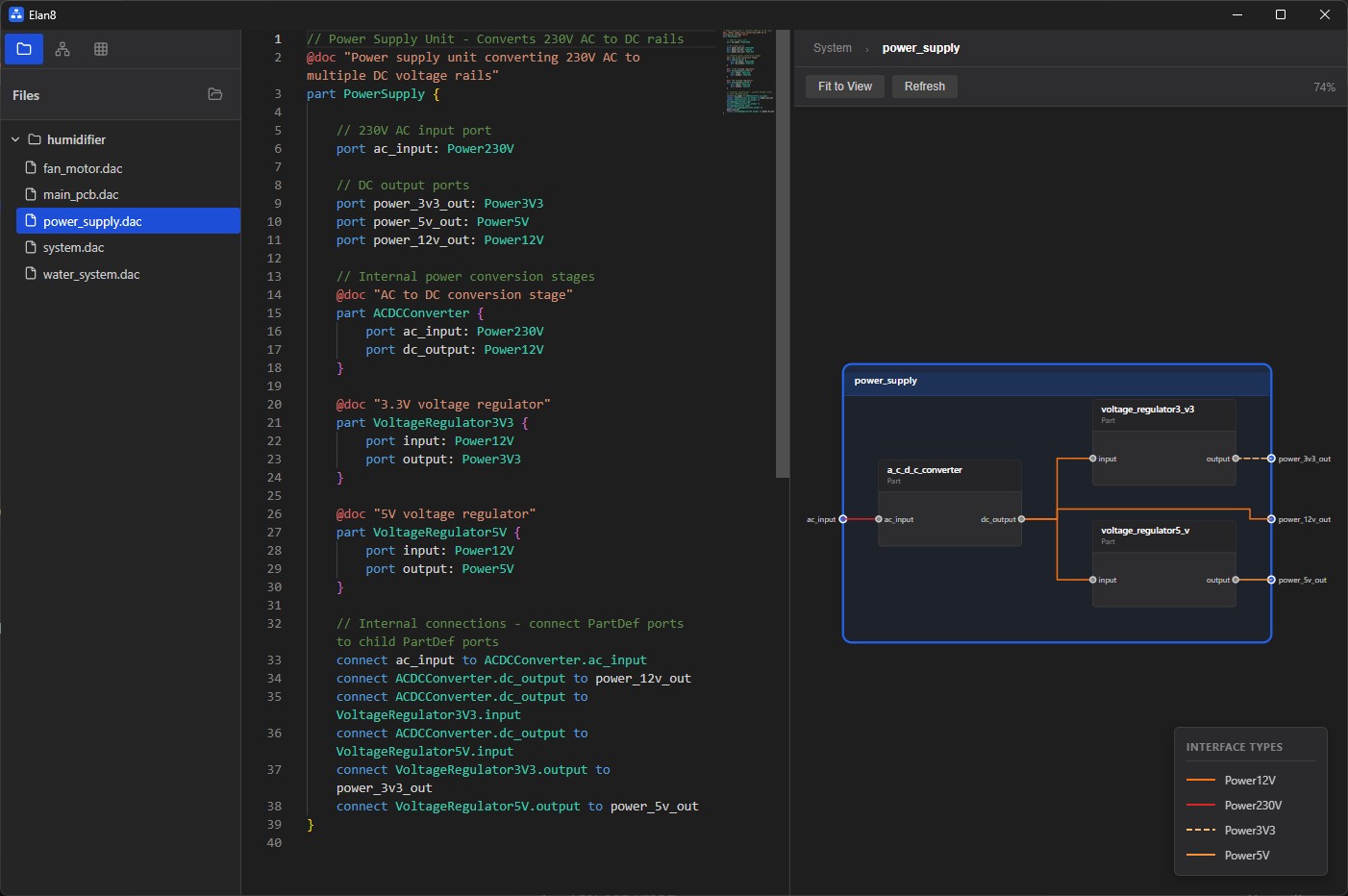
The diagram shows components as blocks, ports as connection points, and interfaces as colored lines. This visual representation helps you understand the architecture at a glance, while the DSL code remains the source of truth.
Design Principles
The Elan8 DSL is designed with specific principles in mind:
Text over diagrams
While visual diagrams are useful for understanding, the DSL prioritizes text-based definitions. Text is versionable, reviewable, and diffable. Diagrams are generated from text, not the other way around.
Explicit interfaces
Interfaces are first-class concepts. Every connection must specify what interface it uses. This makes dependencies explicit and checkable. You can't accidentally connect incompatible components.
Git-friendly diffs
The language syntax is designed to produce clean, readable diffs. Changes to architecture are as easy to review as changes to code. Architecture evolution becomes part of your Git history.
Architecture validation as part of CI
The DSL is designed to be validated automatically. Architecture checks can run in CI/CD pipelines, catching interface mismatches, missing connections, and constraint violations before they cause problems.
Want to Learn More?
This specification covers the core concepts of the Elan8 DSL. For more details about the product and how it works, see the Product page.